

Magazine Archive
Home -> Magazines -> Issues -> Articles in this issue -> View
Article Group: | |
The BLOB | |
Article from International Musician & Recording World, August 1975 | |
A brief description and explanation of "The Blob" as fitted to the International Musician improved copy-guitar. There are many fascinating things one can do with electronics fitted in guitars, however, this simple device is intended to solve only one problem. You may have noticed that many guitars have a less gutsy tone when the volume control(s) are turned down from "Full". I believe there are two possible explanations of this, both of which concern the interaction of pick-up source resistance, volume control resistance, amp input resistance and guitar lead self-capacitance:— in other words, an inconvenient combination of side-effects. The Blob is the simplest way of dealing with the problem from both ends at once. (I don't consider it a priority, to find out which end is most significant.)
If you are interested in more technical details, try reading "Basic Audio Systems" by N.J. Crowhurst (Publ. Foulsham-Tab) pages 162, 163, et. seq. Also "Wireless World" December 1973 pages 585 et. seq.). The Blob is so called, because the prototype was encapsulated in a shapeless lump of Plastic Padding, and this still seems one of the most efficient methods.
The device is built on a tiny scrap of the smaller size of Vero-board, 6 holes and margin, by 4 holes and margin. If you are a "One hole—one wire" purist, you will need a bigger piece of board, or you could design a printed circuit, to fit the exact size of the components you have. The input capacitor is mounted on the copper side of the board, and requires a thick, heatproof case and easily bent leads. I find the 400 volt R.S. components type, with a rectangular green nylon case, very suitable, but if you have difficulty with this, try distributors, DORAM Ltd., or any retail outlet of the manufacturers, Advance Filmcap Ltd. It will be necessary to dress the leads of most components very carefully to fit them into the space without touching each other. You can avoid this difficulty by keeping exactly the same layout, and using the wider-spaced veroboard, but you will have more difficulty fitting the finished device and batteries into your guitar.

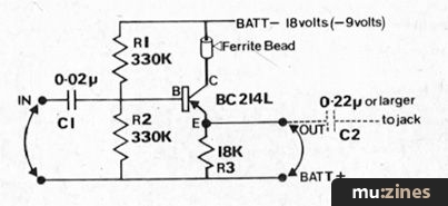
This device requires a supply of about 18 volts from two small batteries, as shown in the June issue. This is quite uncritical, and it will work happily off one battery (9 volts) with a reduced overload margin. Current drain at 18 volts is about 1/2 milliamp, and batteries must be changed about once a month, as the blob will work fairly well off virtually flat batteries, and so give no warning of the chance of leakage. Alternatively, use Duracell batteries; these last much longer, and then rapidly become totally dead.
Diagrams 1 and 2, show the front, and end of the board respectively. The "Emitter end" of R3 is taken through the board and back over the edge, and than bent like a hairpin, and back through the same hole as the Collector, because the transistor leads are too fragile to be used as terminal pins. The wire loop is cut open, after the board is encapsulated in Plastic Padding or similar Polyester Body-filler paste. Other terminals are formed from the leads of R2 and C1. These and the other terminal wires are not cut short after being soldered to the board, but allowed to project through the encapsulating paste.
This form of circuit is known as an "Emitter Follower".
With the components given above it is intended to work into a load of 33 K ohms or more. (Normal Guitar amp).
Contrary to popular opinion, this configuration is not infallibly stable and if it is likely to be used into a low impedance input, you should put a Ferrite Bead (from T.V. repair shops) onto the actual collector lead of the transistor, before assembly.

Components required:
1 off Transistor B C 214 L
2 off Resistors 330 K low noise 1/8 watt
1 off Resistor 18 K low noise 1/8 watt
1 off Capacitor 0.02 microfarad 400 volt or less. (See text)
1 off Capacitor (between Blob & Jack socket) 0.2 microfarad, or larger if loss of bass is noticed into low impedance input.
Veroboard — for size — see text.
Batteries, sleeving, solder, battery clips, etc.
1 SMALL FERRITE BEAD - see text.

More from these topics
 Set It Up! |
 Amdek Hand Clapper Kit |
 Care & Feeding of the Synthesizer |
 Speaker Drive Units - Control Room (Part 1) |
 Keyboard Matrix Interface For EK-3 |
 The Programmable Digital Sound Generator (Part 1) |
 Voltage Controlled Clock |
 Workbench |
 Star Wires - The Wires and Wherefores of Connecting up Your Studio |
 Digital Signal Processing (Part 1) |
 Lab Notes: In Pursuit of the Wild QuASH |
 Tape Machines Line Up Here |
Browse by Topic:
Electronics / Build
Maintenance / Repair / Modification
Publisher: International Musician & Recording World - Cover Publications Ltd, Northern & Shell Ltd.
The current copyright owner/s of this content may differ from the originally published copyright notice.
More details on copyright ownership...

International Musician - Aug 1975
Donated & scanned by: Mike Gorman
In Brief
Feature by Stephen Delft
Previous article in this issue:
Next article in this issue:
Help Support The Things You Love
mu:zines is the result of thousands of hours of effort, and will require many thousands more going forward to reach our goals of getting all this content online.
If you value this resource, you can support this project - it really helps!
Donations for June 2026
Issues donated this month: 0
New issues that have been donated or scanned for us this month.
Funds donated this month: £0.00
All donations and support are gratefully appreciated - thank you.
Magazines Needed - Can You Help?
Do you have any of these magazine issues?
If so, and you can donate, lend or scan them to help complete our archive, please get in touch via the Contribute page - thanks!