


Magazine Archive
Home -> Magazines -> Issues -> Articles in this issue -> View
Build a Headphone Amp | |
Article from International Musician & Recording World, July 1975 | |
For around £4 and a few hours you can have art IM practice/tuning amp
A very useful piece of equipment for the owners' solid guitars is a headphone amplifier. The unit described here is both inexpensive and simple to build and will give satisfactory results with any guitar and almost any headphone. The total cost, including a plastic or metal box in which to build it, should be no more than about £4. This is a cost effective way of hearing ones own music without outside disturbance.


It is an unfortunate fact that both guitar and headphone sensitivities and impedances vary over wide limits. This makes designing a unit which will work with any combination a little difficult. In this design, the output circuit is arranged so that the output power does not vary too mildly when headphones of different impedances are used. Any impedance from 4 to 200 ohms per headphone is satisfactory. The maximum output power is approximately 250mW into 10 ohms. This is the maximum rating of many headphones and creates quite a high sound level. Experience shows that the 'average' guitar gives an output signal of about 30mVRMS with medium strength single note playing. In our unit, this will give full output into the headphones.

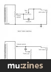
(Click image for higher resolution version)
Construction

For simplicity, an integrated circuit power amplifier has been used. The type chosen in SGS type TBA 820. This comes in a 14 pin plastic package which will fit directly onto standard 0.1in. matrix board (vero board). The copper stripped vero board used for last month's project is, unfortunately, not suitable for the headphone amplifier because, with the TBA 820, wiring must be kept short and direct. Plain vero board, without copper strips, can be used. The components are connected together using their own wires or 22, 24 or 26 swg tinned copper wire.
Connections are made to the I.C. pin and soldering with a small amount of solder. The surplus wire is then cut off. Do not hold the soldering iron on any pin of the I.C. for longer than 10 seconds without allowing the I.C. to cool. One second should be long enough to make a good joint.
The pin numbers of the I.C. are counted counter-clockwise from the dot at one end when looking at the top. The layout may have to be altered a little by some constructors because suitable electrolytic capacitors come in a variety of shapes and sizes and those purchased by a constructor may not be exactly the same as those I have used.
In the components list, a minimum and a maximum value for each capacitor is given. C2, C3 and C6, determine the bass response. For ordinary guitars, the minimum values are all right but for bass guitar, the 'preferred' or maximum value should be used. Note that electrolytics have a correct and an incorrect way round; usually denoted by a + or - or a ring around the -ve end or a red spot on the +ve end. No electrolytic capacitors and the resistors can go either way round.

The on/off switch can be fitted in several different ways. The volume control can be brought with a switch on; a separate switch could be fitted or a jack socket of the type with a switch on, which switches off when the plug is withdrawn, could be used. If the output jack socket carries the switch, then a simple contact which makes to the sleeve part of the socket when a plug is inserted is satisfactory. If the input socket carries the switch; the switch part must be completely isolated electrically from the jack earth contact or the amplifier may 'hoot' by itself.
Any 9 volt battery can be used. A PP3 will last a reasonable time, a PP6 for rather longer and a PP9 for a very long time. A 6 volt battery is also suitable but will give rather less output power to the earphones; but this could be an advantage.
The form of construction is self evident from the photographs. Any metal, plastic or wood box will suit and it need be only half the size of the metal Radio Spares box used for the prototype.

(Click image for higher resolution version)

| REF. | VALUE | RATING | DESCRIPTION | ||
| min. | preferred | max. | |||
| IC1 | TBA 820 integrated circuit | ||||
| R1 | 47 | 56 | 68 | ||
| R2 | 47 | 56 | 68 | ¼ or 1/8 watt Resistor | |
| R3 | 47 | 10 | 12 | ||
| R4 | 47 | 10 | 12 | ¼ or ⅓ watt Resistor | |
| C1 | 47u | 100u | 220u | Not less than 10y wk. | Electrolytic Capacitor |
| C2 | 47u | 100u | 220u | Not less than 10y wk. | Electrolytic Capacitor |
| C3 | 47u | 100u | 220u | Not less than 10y wk. | Electrolytic Capacitor |
| C4 | 86p | 100p | 120p | Not less than 10y wk. | Ceramic or silver mica capacitor |
| C5 | — | 0.1u | 0.22 | Not less than 10y wk. | (Ceramic preferred) capacitor |
| C6 | — | 0.1u | 0.22 | Not less than 10y wk. | (Ceramic preferred) capacitor |
| C7 | 330u | 470u | 1000u | Not less than 10y wk. | Electrolytic capacitor |
| VR1 | 47K | 100K | 220K | Logarithemic low Carbon pot. | |
| Stereo jack socket | |||||
| Vero pins | |||||
| Mono jack socket | |||||
| Battery clip | |||||
| On/off switch | |||||
| Suitable metal or plastic box | |||||
| Vero board—plain type | |||||
More with this topic
 HSR Stereo Autofader Project (Part 1) |
 How It Works - Drum Machine |
 The Spectrum Synthesiser - Professional Quality Monophonic Instrument (Part 1) |
 Electro-Music Engineer - Transistor Power Amplifier Surgery |
 Technically Speaking |
 A Low Cost, Special Purpose AR Generator |
 Adding Fine Tuning To Standard Controls |
 Digital Signal Processing (Part 1) |
 Workbench - Signal Processors - Frequency Response Modification |
 Trigger Converter for the Yamaha SPX-90 |
 The Ins and Outs of Digital Design |
 Workbench - Modifying The Midiverb |
Browse by Topic:
Electronics / Build
Publisher: International Musician & Recording World - Cover Publications Ltd, Northern & Shell Ltd.
The current copyright owner/s of this content may differ from the originally published copyright notice.
More details on copyright ownership...

International Musician - Jul 1975
Donated & scanned by: Mike Gorman
Feature
Help Support The Things You Love
mu:zines is the result of thousands of hours of effort, and will require many thousands more going forward to reach our goals of getting all this content online.
If you value this resource, you can support this project - it really helps!
Donations for April 2026
Issues donated this month: 0
New issues that have been donated or scanned for us this month.
Funds donated this month: £0.00
All donations and support are gratefully appreciated - thank you.
Magazines Needed - Can You Help?
Do you have any of these magazine issues?
If so, and you can donate, lend or scan them to help complete our archive, please get in touch via the Contribute page - thanks!